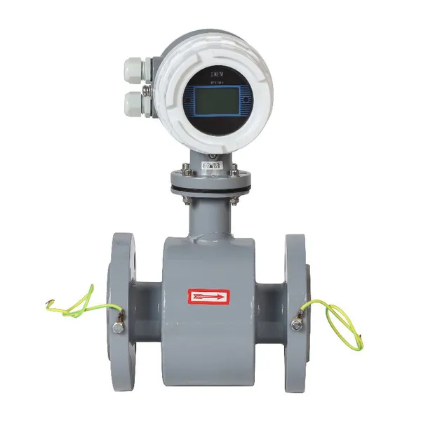
 Business License
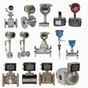
The importance of installing flow meters
Installation Precautions for Gas Turbine Flowmeters
1. Straight Pipe Section Requirements (Critical for Measurement Accuracy)
Sufficient straight pipe without turbulence shall be reserved at both upstream and downstream of the meter. D refers to the nominal diameter of the flowmeter:
Upstream straight pipe: ≥10D (no valves/elbows); ≥10D for single 90° elbow; ≥20D for two vertical 90° elbows; ≥8D for fully open gate valve; ≥25D for globe valve / pressure regulating valve.
Downstream straight pipe shall be at least 5D.
Only concentric tapered reducers/expanders are allowed for pipe diameter transition. Eccentric reducers are forbidden as they cause biased gas flow.
Keep the meter far away from strong turbulence equipment such as compressors and blowers.
2. Installation Direction & Position
Gas flow direction must align with the arrow marked on the meter body; reversed installation will stop the impeller and lead to zero measurement.
Horizontal installation is preferred. Vertical installation is only acceptable when gas flows upward from bottom to top. Vertical downward installation is strictly prohibited, as liquid and dust will accumulate and jam the impeller bearing.
Ensure coaxial alignment of flanges. Do not force or twist the meter to correct misalignment, which may deform the body and block the impeller.
3. Matching Pipeline Accessories
Install a Y-type strainer (80~100 mesh screen) on the upstream side to block welding slag, dust and solid particles from wearing the impeller and bearings; mandatory for gas with impurities.
For humid or low-temperature gas, install condensate pots and drain valves upstream to discharge liquid regularly. Residual liquid inside will corrode internal parts and cause inaccurate readings.
Adopt a three-valve set (inlet shut-off valve, outlet shut-off valve, bypass valve) to maintain pipeline gas supply during meter maintenance.
Pressure regulating valves and control valves shall be mounted at the front end of the straight pipe section instead of close to the flowmeter. Turbulence generated by throttling will greatly reduce measuring precision.
4. Working Medium Limitations
The measured gas shall be dry and clean. A gas-liquid separator is required if the medium contains massive droplets, oil or dust.
Operating temperature and pressure shall not exceed the rated parameters of the meter. Fit heat dissipation brackets for high-temperature working conditions, and add thermal insulation to avoid freezing under low temperature.
Open and close pipeline valves slowly to avoid instant high pressure and high flow impact that may deform or damage the impeller blades.
5. Wiring & Explosion-Proof Specifications
Use shielded dedicated cables between split sensor and display transmitter, routed in separate metal conduits. Keep cables clear of power cables for inverters and large motors to avoid electromagnetic interference.
Reliable single-point grounding for meter housing and cable shielding layers. Follow full explosion-proof construction standards for hazardous areas.
Equip explosion-proof cable glands and flexible conduits in explosive zones; cables shall be intact without exposed copper wires.
Maintain stable power supply to prevent abnormal signals caused by voltage fluctuation.
6. On-site Environmental Protection
Install rain and sun protection enclosures for outdoor meters to prevent circuit damage from rainwater infiltration.
Keep away from high-temperature heat sources and strong vibration equipment such as compressors. Long-term vibration will wear bearings and damage sensing probes.
Avoid open fire and static electricity sources for explosion-proof installation.
Recently Posted
-
Swirl flow meters vs. Vortex flow meters
July 8, 2026Both Swirl flow meters and Vortex flow meters belong to the category of fluid vibration flow meter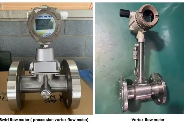 Read More
 -
Gas Ultrasonic Flow Meters: Solve Major Problems For Gas Companies
July 8, 2026In recent years, with the acceleration of urbanization and the increase in the penetration rate of natural gas, gas compani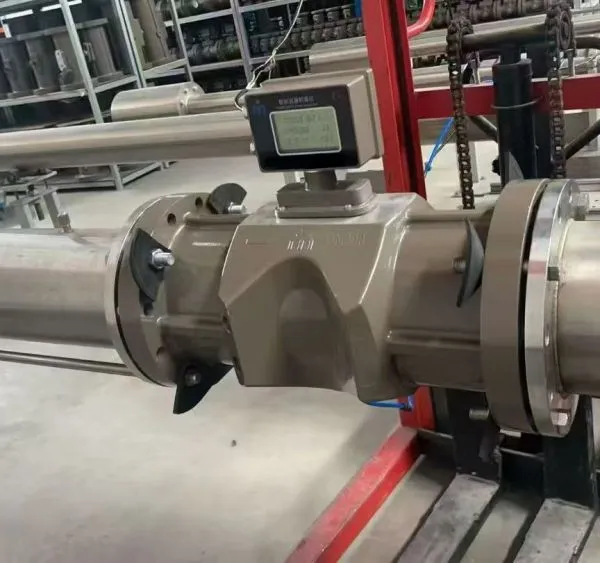 Read More

Contact Us
Recommended Products
-
 Intelligent Pipeline Mounted Turbine Flowmeter for Flow MeasuringUS$ 115 - 845MOQ: 1 Set
 -
Pulse / 4-20mA Liquid Diesel Fuel Oil Turbine Flow Meter FlowmeterUS$ 115 - 845MOQ: 1 Set
-
High-Precision Stainless Steel RS485 Digital Turbine Flow Meter for WaterUS$ 115 - 845MOQ: 1 Set
-
Precision Stainless Steel Liquid Turbine Flow Meter for Water Gasoline DieselUS$ 115 - 845MOQ: 1 Set
-
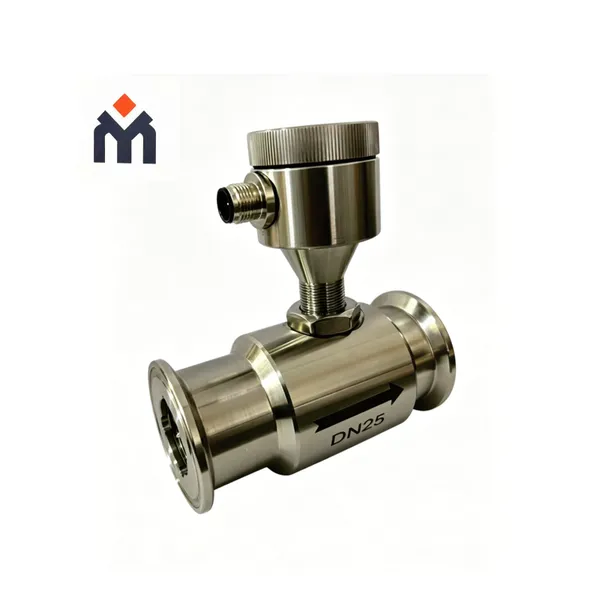
Digital RS485 Food Grade SUS316L Tri-Clamp Liquid Milk Pure Water Turbine Fuel Flow MeterUS$ 115 - 845MOQ: 1 Set
-
RS485 Modbus RTU Liquid Diesel Oil Turbine Flow MeterUS$ 115 - 845MOQ: 1 Set
-
Factory Positive Displacement Flowmeter Fuel Diesel Oval Gear Flow MeterUS$ 450 - 650MOQ: 1 Set
-
High Accuracy Mechanical Bitumen Oval Gear Flow MeterUS$ 450 - 650MOQ: 1 Set
-
Mechanical Diesel Oval Gear Flow Meter Positive Displacement FlowmeterUS$ 450 - 650MOQ: 1 Set
-
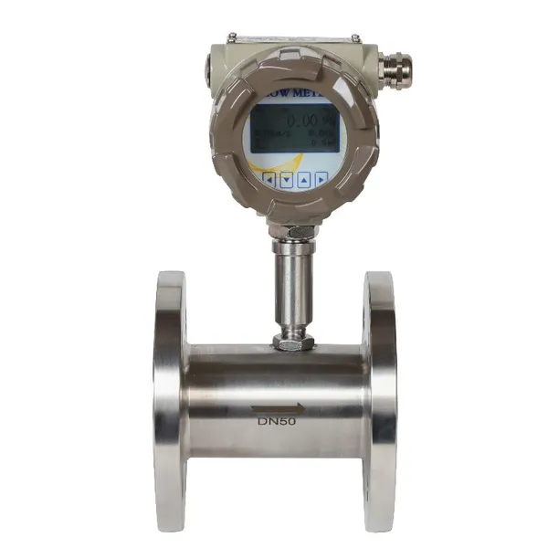
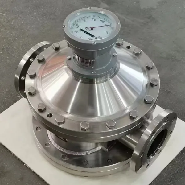
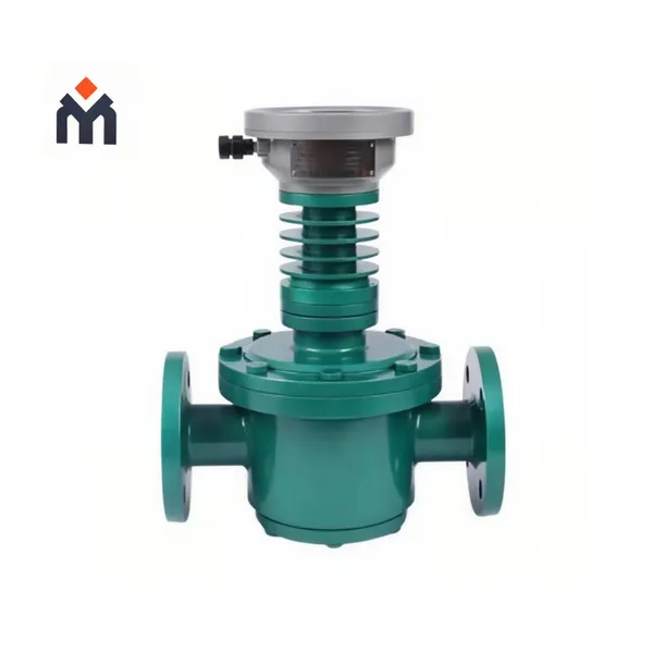
High Accuracy Digital Fuel Oil Diesel Measurement Gear Positive Displacement Flow MeterUS$ 450 - 650MOQ: 1 Set
-
Digital RS485 High Viscosity Liquid Gear Flow Meter for OilUS$ 450 - 650MOQ: 1 Set
-
High Accuracy Digital Remote Type Gear Flowmeter for Liquid Oil Fuel MeasurementUS$ 450 - 650MOQ: 1 Set
-
Digital High Viscosity Asphalt Positive Displacement Flow MeterUS$ 450 - 650MOQ: 1 Set
-
4-20mA Positive Displacement Fuel Tanker Measurement Flow MeterUS$ 450 - 650MOQ: 1 Set
-
Factory Liquid Micro Gear Flowmeter for High Viscosity Hydraulic Oil/Resin/GlueUS$ 450 - 650MOQ: 1 Set
-
Digital High Viscosity Stainless Steel Micro Gear Oil Flow MeterUS$ 450 - 650MOQ: 1 Set
-
Factory Price Digital Integrated Cast Steel Water Electromagnetic FlowmeterUS$ 240 - 2260MOQ: 1 Set
-
Integrative Emf Liquid Electromagnetic Flow Meter for Water MilkUS$ 240 - 2260MOQ: 1 Set
-
Digital Remote Type RS485 Liquid Electromagnetic Flow MeterUS$ 240 - 2260MOQ: 1 Set
-
China Intelligent Liquid Electromagnetic Flow Meter High Precision And Reliable MeasurementUS$ 240 - 2260MOQ: 1 Set